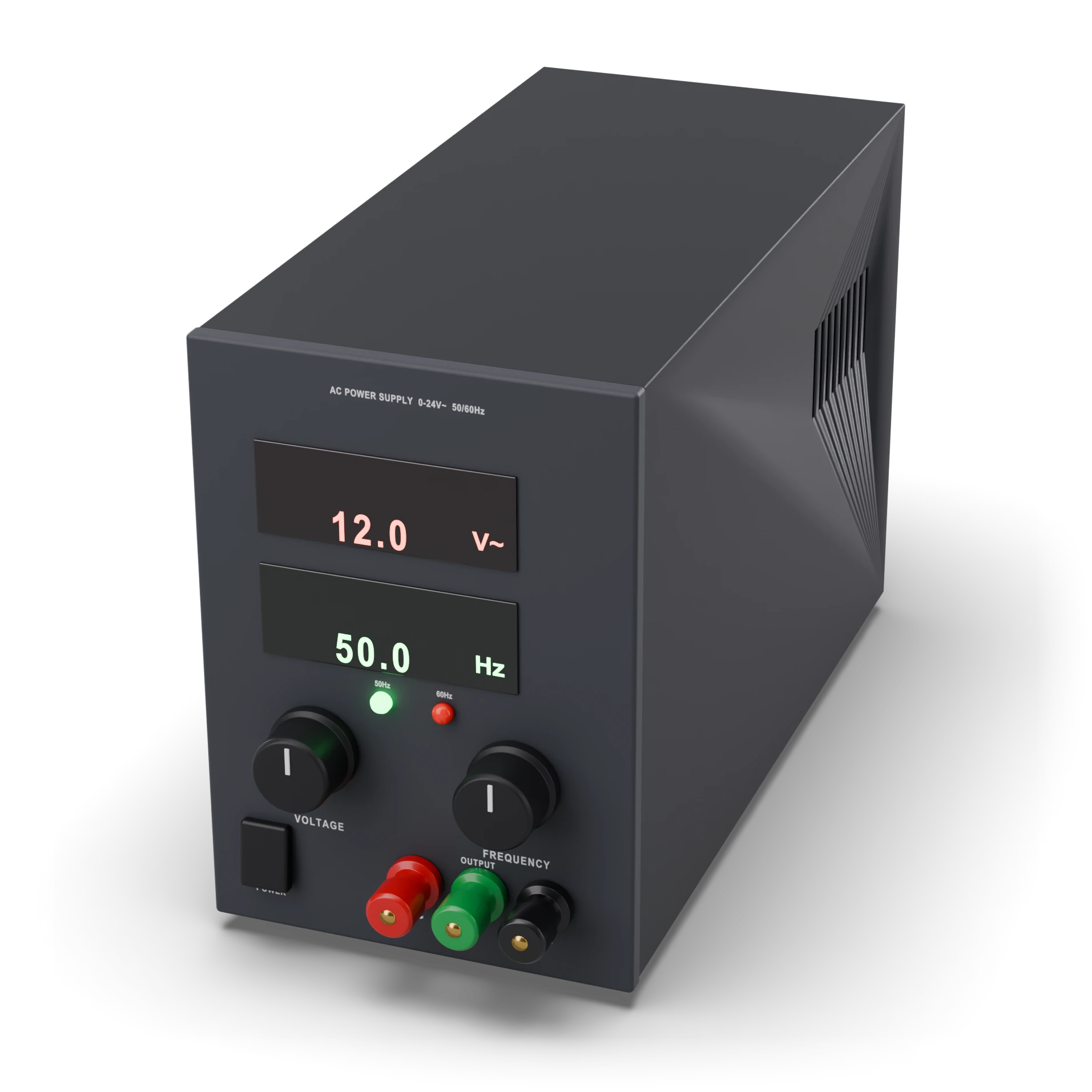
- 1Voltage indicator (V~, effective value)
- 2Frequency indicator (Hz)
- 3Voltage setting
- 4Frequency setting (50 / 60 Hz)
- 5On / off switch
- 6Output terminals (~ red, ~ black) · green: chassis ground
Enclosed adapter box or benchtop generator; size depends on the model
AC source (12 V~ 50 Hz adapter / signal generator)
Electricity that keeps changing direction. It goes back and forth like a pump pushing water to and fro.
It is the starting point for rectifier and filter experiments; unlike a battery, it does not flow in one direction only.
The electricity in a wall socket comes and goes like this too; on the bench we use a safe, low-voltage version of it.
A closed adapter box or a desktop device with knobs; it has two output terminals and no plus or minus.
Never connect it to a wall socket yourself; use only an insulated, low-voltage adapter.
A source whose voltage changes direction over time. An isolated 12 V~ adapter supplies a 50 Hz sine; a signal generator is a source with adjustable waveform and frequency, usually with less current. The Lab uses low voltage only; a mains outlet is not an experiment source.
IEC 60617: the drawing style used in Türkiye and Europe.
- Voltage
- 12 V RMS (adapter example)
- Frequency
- 50 Hz (adapter example)
- Wave
- Sine; adjustable on the generator
- Peak voltage
- ≈17 V (12 V RMS sine)
- Peak-to-peak
- ≈34 V (12 V RMS sine)
- Output current
- By the adapter’s VA rating / the generator’s limit
- Generator load
- Typically 50 Ω output; the load setting affects the amplitude
- Safety
- Isolated low-voltage output; no mains in the Lab
- Example part
- Isolated 12 V~ 50 Hz adapter; a signal generator as an alternative
Test with a multimeter
Test whether this part is good with the multimeter on the measurement screen.
Take a measurement