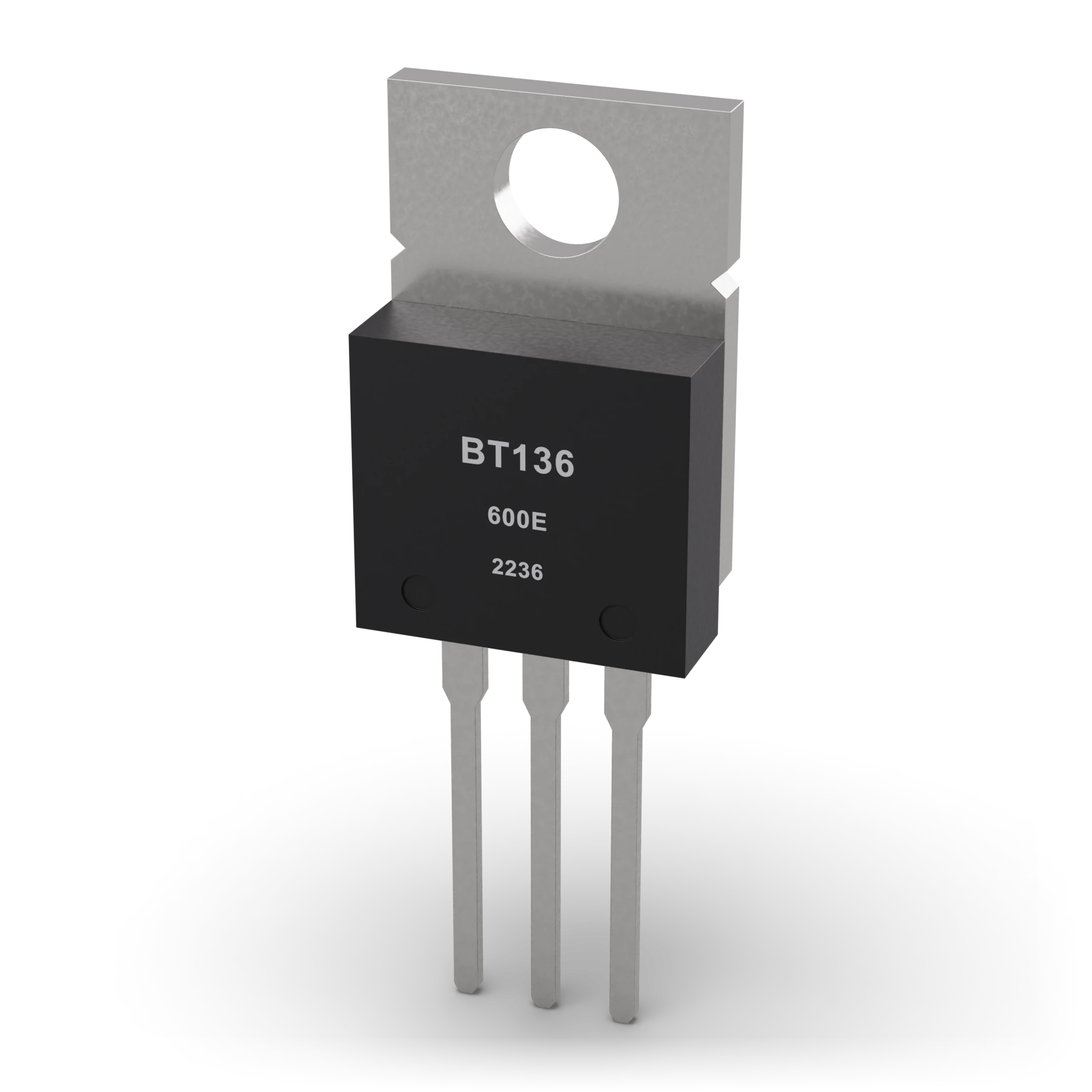
- 1Metal tab (heat sink) · Ø 3.7 mm hole
- 2Epoxy body
- 3Pins MT1-MT2-G · 2.54 mm spacing
TO-220 body ≈ 10 × 15 mm; pin pitch 2.54 mm
Triac (BT136)
An electronic gate that passes current in both directions and opens with a small nudge.
Turns on an alternating-current load with a small trigger current; it is the working principle of a light dimmer.
Inside wall light dimmers.
Black body with three pins and one face with a metal tab; the pins are MT1, MT2 and gate.
The metal tab can be live too, so don’t touch it; the part does not switch off immediately when you cut the gate current.
A power semiconductor that can conduct current in both directions and is triggered by gate current. Once triggered, it keeps conducting even after the gate signal is removed, as long as the current stays above the holding current. In AC it turns off when the current nears zero. Unlike a transistor, it cannot cut a continuous DC current by turning off the gate.
IEC 60617: the drawing style used in Türkiye and Europe.
- Load current
- 4 A RMS (with proper cooling)
- Blocking voltage
- 600 V
- Gate trigger (IGT)
- ≈5–35 mA; varies by version, temperature and region
- BT136-600E IGT
- Max. 10 mA (I–III), 25 mA (IV), 25 °C
- Holding current (IH)
- ≈10–20 mA class; 600E max. 15 mA, 25 °C
- Closing
- When the load current drops below IH
- Cooling
- Depends on power dissipation and ambient temperature
- Lab limit
- Low-voltage AC only; mains is out of scope
- Example part
- BT136-600E, TO-220
Test with a multimeter
Test whether this part is good with the multimeter on the measurement screen.
Take a measurement