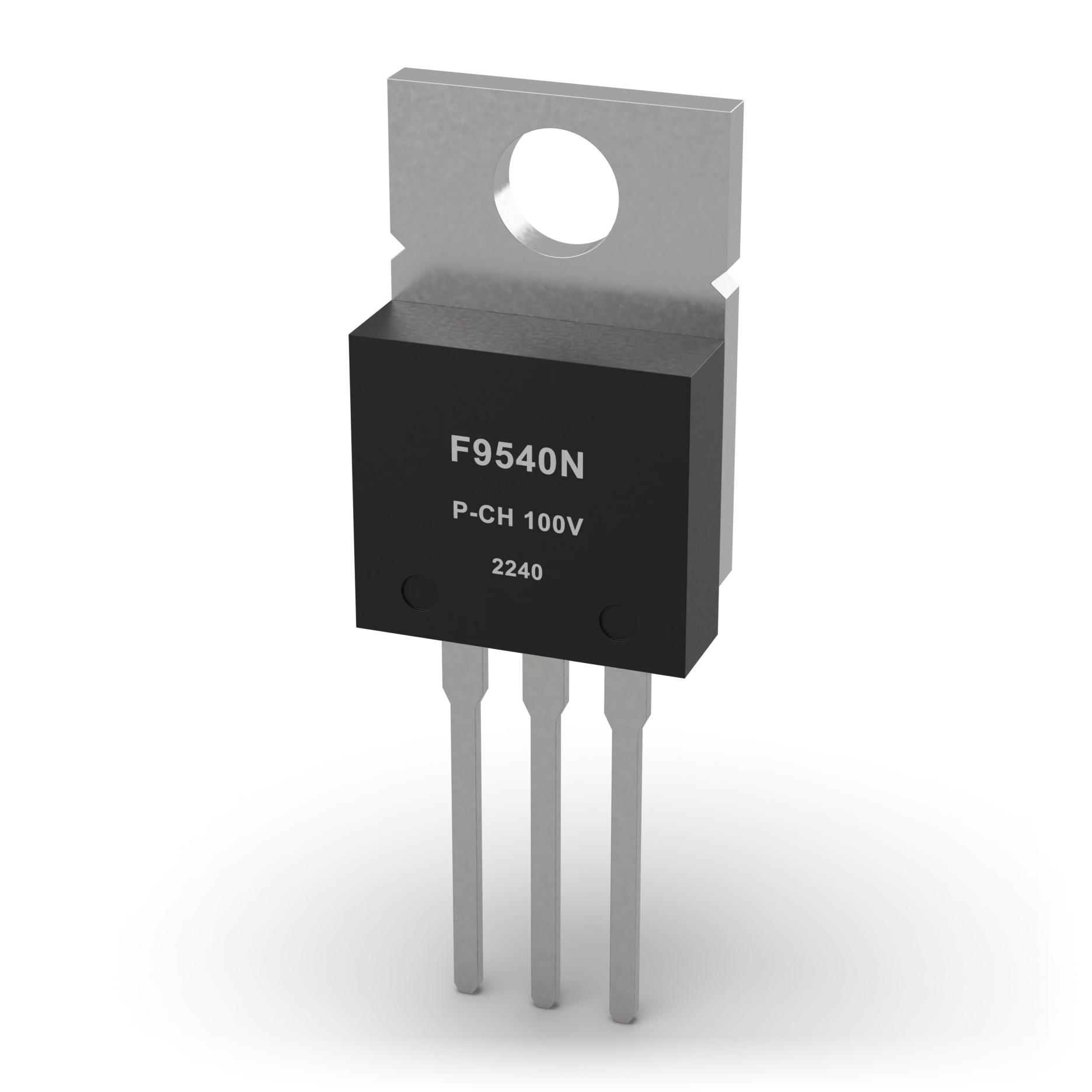
- 1Metal tab (heat sink) · Ø 3.7 mm hole
- 2Epoxy body
- 3Pins G-D-S · 2.54 mm spacing
TO-220 body ≈ 10 × 15 mm, metal tab with a hole · Example shown: IRF9540N-class P-channel MOSFET, TO-220
P-channel MOSFET
The mirror image of the N-channel; a valve that opens when its gate is pulled down.
It switches the positive side of the load; it also protects against a battery connected in reverse.
In battery-powered devices, in power cut-off and reverse battery protection circuits.
A body with a metal tab and three legs; you tell it apart from the N-channel by the code on top.
The source goes to the plus supply; if you mix it up with an N-channel, it will not turn on. It is sensitive to static electricity.
The complement of the N-channel MOSFET: the source connects to the positive supply and it conducts when the gate is pulled down relative to the source. Used for a positive-side switch and reverse polarity protection. Its on-resistance is higher than an N-channel of the same size.
IEC 60617: the drawing style used in Türkiye and Europe.
- VDS
- −100 V
- ID (continuous)
- −23 A
- RDS(on)
- ≤ 0.117 Ω (VGS −10 V)
- VGS(th)
- −2 … −4 V
- Max. VGS
- ±20 V
- Driving
- Pull the gate ≈10 V below the source
- Package
- TO-220
- Example part
- IRF9540N (TO-220)
Test with a multimeter
Test whether this part is good with the multimeter on the measurement screen.
Take a measurement