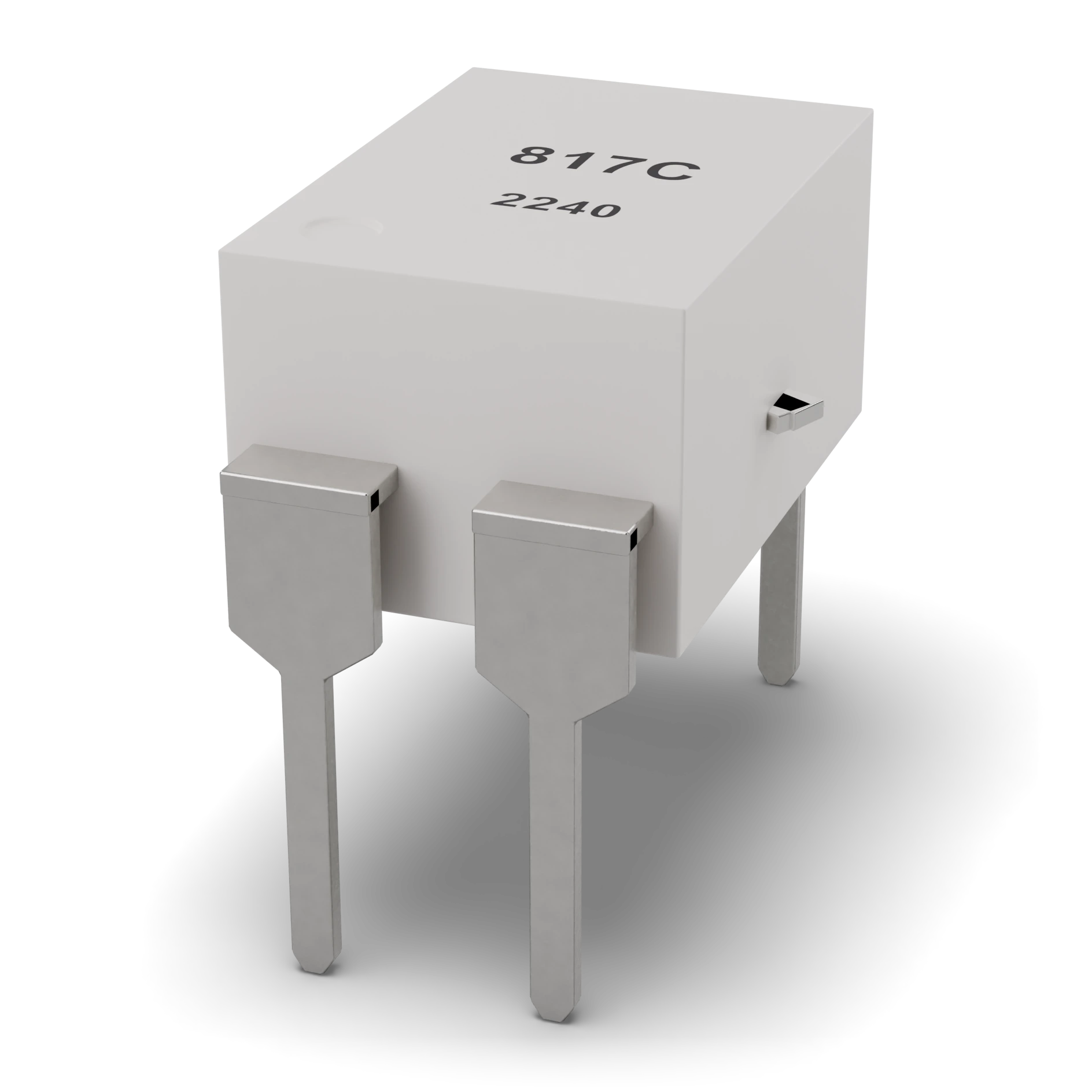
- 1White molded body · DIP-4
- 2Pins (1-2 LED, 3-4 transistor)
Body ≈ 6.5 × 4.6 mm; row spacing 7.62 mm, pin pitch 2.54 mm
Optocoupler (PC817)
A part whose two rooms talk through light. A small lamp lights in one room, and the eye in the other room sees it.
Carries the signal of one circuit to another without an electrical connection; noise and harmful voltage do not pass.
A small black IC, found in chargers and adapters, that separates the mains side from the low-voltage side.
A small black body with four pins; two pins are for the LED inside, two for the light-sensing transistor.
Put a series resistor in for the LED inside; if you join the grounds of the two sides, the isolation is wasted.
A DIP-4 package holds an infrared LED and an NPN phototransistor facing it. Input current becomes light, and light becomes output current; there is no conductive connection between the two sides. CTR is the ratio of the output collector current to the input LED current and varies widely by part class.
IEC 60617: the drawing style used in Türkiye and Europe.
- CTR
- 50–600% (IF = 5 mA, VCE = 5 V, 25 °C)
- LED current (IF)
- 50 mA absolute max.; 5–10 mA in the experiment
- Isolation (Viso)
- 5 kV RMS, 1-minute test
- LED forward voltage
- ≈1.2 V (20 mA)
- VCEO
- 80 V (PC817X; 35 V in older versions)
- Collector current
- 50 mA absolute max.
- VCE(sat)
- ≤0.2 V (IF = 20 mA, IC = 1 mA)
- Speed
- µs range; may not be suitable for fast data
- Example part
- Sharp PC817X, DIP-4
Test with a multimeter
Test whether this part is good with the multimeter on the measurement screen.
Take a measurement