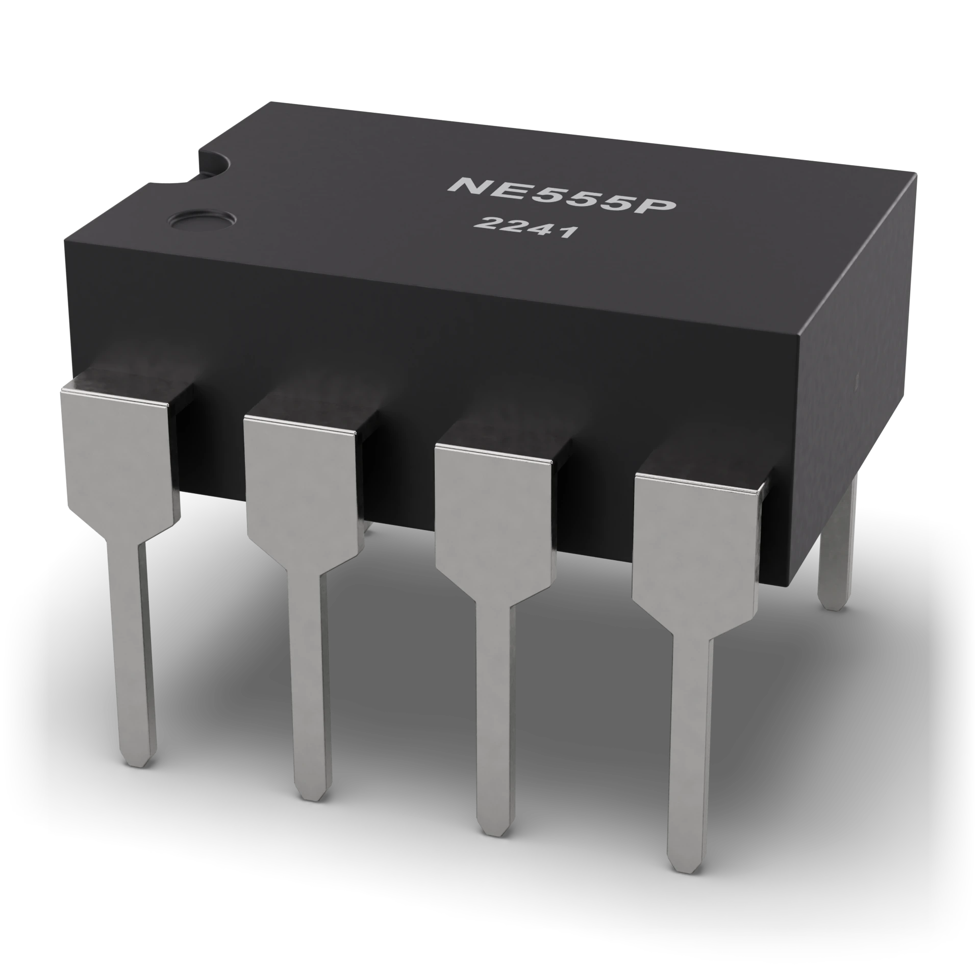
- 1Pin 1 notch
- 2NE555P timer
- 3Pin 1 dot
- 4Epoxy body (DIP-8) · 9.6 × 6.35 mm
- 5Pins (2.54 mm pitch)
DIP-8: body ≈ 9.8 × 6.4 mm, pin pitch 2.54 mm, row spacing 7.62 mm
555 timer
A tiny metronome: you set the speed of its ticking with the resistor and capacitor you connect from outside.
Makes an LED blink, produces a beep tone, or switches something on and off with a small delay.
In blinking decorative lights and simple alarms.
A black IC with eight legs (two rows of four), with 555 printed on top; the notched end points to the first leg.
Place it the right way round using the notched end; do not reverse the supply and ground pins.
A timer IC containing two comparators, a flip-flop and a discharge transistor. You set the times with an external resistor and capacitors. In astable mode it produces a square wave on its own; in monostable mode it produces a single pulse when triggered.
IEC 60617: the drawing style used in Türkiye and Europe.
- Power supply
- 4.5–16 V
- Output current
- ≤ 200 mA (source or sink)
- Power supply current
- ≈3–6 mA (5 V)
- Thresholds
- 1/3 VCC and 2/3 VCC
- Astable frequency
- f ≈ 1.44 / ((R1 + 2·R2) · C)
- Monostable time
- t ≈ 1.1 · R · C
- CMOS versions
- TLC555 · LMC555 (low voltage and current)
- Example part
- NE555P (DIP-8)
Test with a multimeter
Test whether this part is good with the multimeter on the measurement screen.
Take a measurement