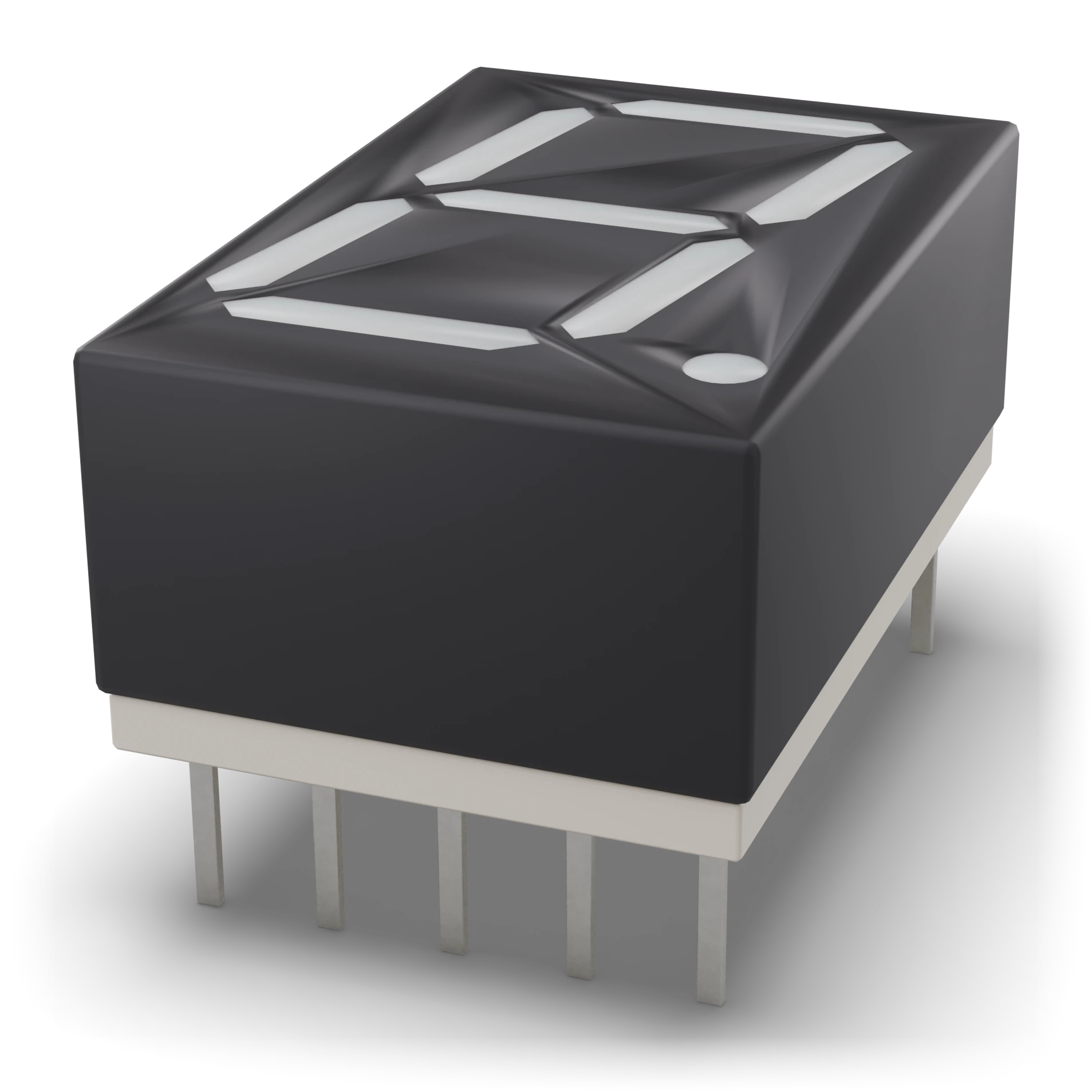
Segment (a–g) · red diffuserBody (reflector) · 12.6 × 19 mmDecimal point (DP)Pins (2 × 5, common cathode)
- 1Segment (a–g) · red diffuser
- 2Body (reflector) · 12.6 × 19 mm
- 3Decimal point (DP)
- 4Pins (2 × 5, common cathode)
Rectangular body with a black face, figure-eight segments and a dot, five legs on the bottom and five on top
0.56 inch single digit: ≈ 12.7 × 19 mm, 10 legs
0.56 inch single digit: ≈ 12.7 × 19 mm, 10 legs
7-segment display
In simple terms
What is this?
A small display that draws digits with bars; seven small LED bars.
What is it for?
Shows a digit depending on which bars it lights.
Where do you see it?
Digital clock, microwave oven and thermometer.
How do you spot it?
Rectangular body with seven bars shaped like an eight and a dot on top; two rows of pins, one at the bottom and one at the top.
Caution:
Give each bar its own resistor; check whether the common pin is a cathode or an anode.
Technical definition
A display made of seven bars (a to g) and one dot (dp) LED that form the digits. In the common cathode type all cathodes are joined, in the common anode type all anodes. Each segment needs its own current-limiting resistor.
TypeCommon cathode / anode
Vf≈2 V (red)
Current≈10 mA / segment
Schematic symbol Same in IEC and ANSI
IEC 60617: the drawing style used in Türkiye and Europe.
Pins 10
1eSeen from the front: bottom row, 1 from left.e
2dBottom row, 2 from left.d
3Common cathodeMiddle of bottom row; GNDCOM
4cBottom row, 4 from left.c
5dp (dot)Bottom row, far rightdp
6bTop row, far rightb
7aTop row, 2 from the right.a
8Common cathodeMiddle of the top row; joined to pin 3COM
9fTop row, 2 from the left.f
10gTop row, far leftg
Features typical
- Segment Vf
- ≈1.8–2.2 V (red)
- Segment current
- ≈10 mA (20 mA max.)
- Pin count
- 10 (two common pins)
- Types
- Common cathode (5161AS) · common anode (5161BS)
- Resistor
- At 5 V ≈330 Ω / segment
- Example part
- 5161AS (0.56 inches, common cathode)
Common mistakes
Putting a single resistor on the common pinWith a single resistor, brightness drops as more segments light up. Put a separate resistor on each segment.
Connecting it without knowing the typeOn a common anode, the common leg goes to positive and a segment lights when its leg is pulled to ground. First measure its type with diode mode.
Test with a multimeter
Test whether this part is good with the multimeter on the measurement screen.
Take a measurementWhere it is used
Counter and timerDigital clockThermometer displayScoreboard
Related lessons