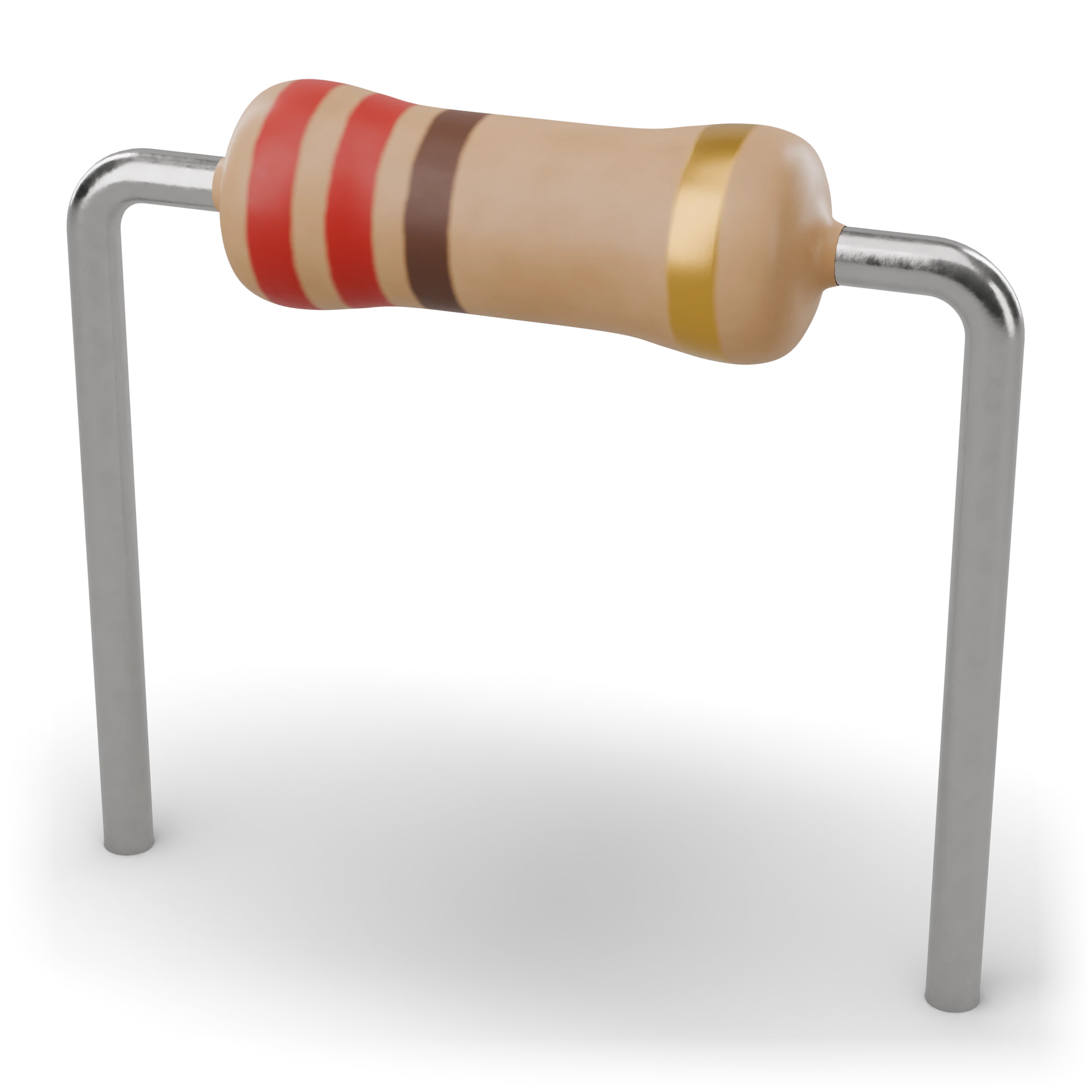
- 1Lacquer coating and color bands · red-red-brown-gold = 220 Ω 5%
- 2Tolerance band (gold = 5%)
- 3Pins (tinned copper)
Body ≈ 6.3 × 2.4 mm, leg ≈ 28 mm
Carbon film resistor
A narrow pipe the electricity passes through. As the pipe narrows, the flow decreases; the resistance value shows how narrow it is.
Limits the current; placed in front of an LED so it does not burn out, and it can also divide voltage.
Small cylinders on the board of cheap toys and radios.
Small cylindrical body with two pins; it has four colored rings on it.
Don't start reading the bands from the reverse end, and don't exceed its power rating; an overloaded resistor heats up.
A fixed resistor made by coating a thin carbon layer on a ceramic rod. Its value is read from four color bands on the body. Being cheap, it is found in most hobby circuits.
IEC 60617: the drawing style used in Türkiye and Europe.
Reading direction: hold it with the tolerance band (usually gold) on the right. If you are color-blind, read the value from the text above.
- Power
- 0.25 W (70 °C)
- Tolerance
- ±5% (gold band)
- Value range
- 1 Ω – 10 MΩ
- Value series
- E24
- Max. operating voltage
- 250 V
- Operating temperature
- −55 … +155 °C
- Example part
- CF 1/4 W (CFR-25)
Test with a multimeter
Test whether this part is good with the multimeter on the measurement screen.
Take a measurement