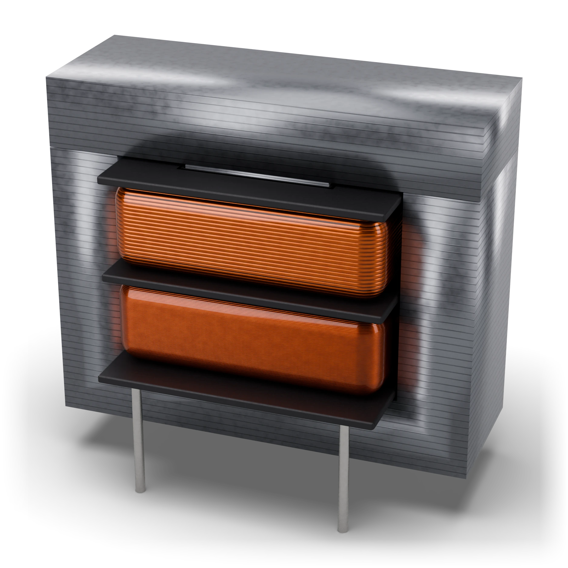
- 1EI core (silicon steel) · EI-30
- 2Secondary winding (thick wire) · 12 V
- 3Bobbin (former)
- 4Primary winding (thin wire, many turns) · 24 V
- 5Pins (primary / secondary)
EI30 core width ≈ 30 mm; overall body and pin spacing depend on the manufacturer
Transformer (24 V / 12 V, EI30)
A translator made of two coils side by side. It passes electricity from one side to the other not through a wire but through a magnetic field.
It steps a high voltage down to a safe low voltage and separates the two sides from each other.
Inside old, heavy adapters and the doorbell transformer.
A square body of stacked iron layers; two terminals on one side for high voltage and two on the other for low voltage, four in total.
Do not touch the high-voltage side; never feed the transformer DC like a battery, its winding will burn.
A component in which two separate windings transfer energy through a common magnetic core. AC current in the primary creates a changing magnetic flux; a voltage is induced in the secondary according to the turns ratio. This example is not an autotransformer; its windings are electrically isolated. The Lab uses only low voltage; the 230 V primary is not for a real connection experiment. That is why the part in the Lab is a safe 24 V / 12 V test transformer.
IEC 60617: the drawing style used in Türkiye and Europe.
- Primary (Lab)
- 24 V RMS AC
- Secondary (Lab)
- 12 V RMS AC
- Turns ratio (Lab)
- 2:1
- Primary current limit (Lab)
- Overload above 150 mA
- Winding resistance (Lab)
- Primary 4 Ω, secondary 1.5 Ω
- Isolation
- Separate primary and secondary; test voltage depends on the series
- No-load voltage
- May be higher than the rated value; depends on regulation
- Real example: primary
- 230 V AC, 50 Hz (mains transformer; not in the Lab)
- Real example: power
- 1.5–2 VA; secondary 12 V RMS, ≈125–167 mA
- Real example: ratio
- ≈19.2:1 nominal; the turns ratio may differ with regulation
- Lab limit
- Low-voltage model only, no real primary connection
- Example part
- Lab: EI30, 24 V / 12 V test transformer; real example: EI30, 230 V / 12 V, 1.5–2 VA isolation transformer
Test with a multimeter
Test whether this part is good with the multimeter on the measurement screen.
Take a measurement